HOW TO CREATING INTEGRATION BETWEEN INSPINIA AND BTICINO
1.INSIPINIA TOUCH PANEL SETTINGS
- Operation voltage (24VDC)
- Communication with ethernet connection
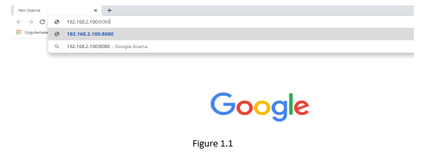
- You need to make sure that your PC and your intercom is connected to the same network as INSPINIA. After the Inspina Touch panel is opened, 8080 is added to the end of the product IP address(Default IP =192.168.2.100) to access the product Web interface via the web browser.(Figure 1.1)
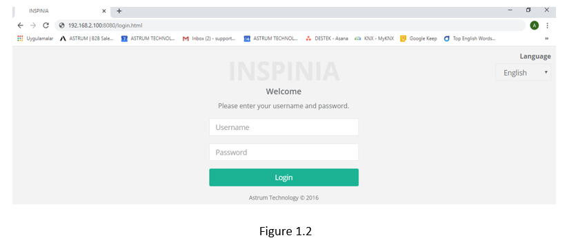
- You can access the user interface as shown in the below picture. User interface (Figure 1.2) Username = admin / Pasword= admin (New version’s password: 4W3FVG)
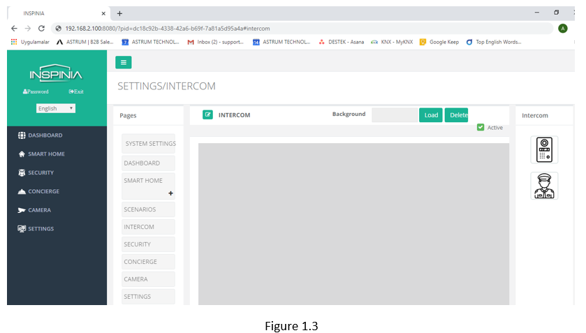
- Click the intercom tab in the settings section for configuration.(Figure 1.3)
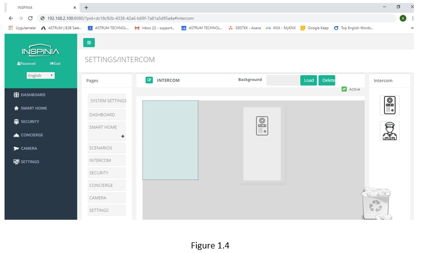
- Drag and Drop the image on the right. (Figure 1.4)
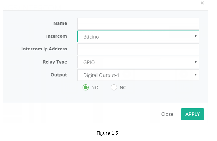
- You can make settings after double click the image (Figure 1.5)
- Name = Text the Device’s name (A Block )
- Intercom = Choose the Intercom type (Bticino)
- Intercom Ip Address = Text the Intercom Ip Address (Bticino)
- Relay type = = Choose the Relay Type
a) GPİO = Touch panel output control
Output = Choose the Relay output which you want to control with
b) BUS = Relay control with Bus Line
Bus adress= Ip address of the relay module
c) Ip module =Control with smart Ip relay
Ip Address= Ip address of the smart relay
2. BTICINO INTERCOM SETTINGS FOR VILLA
You must use the FULLIPSuite programs for configüration BTICINO Intercom. (Figure 2.1)
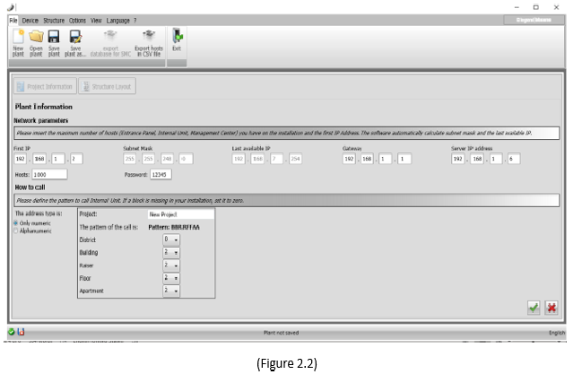
- Firstly,Run the program (Figure 2.2)
First IP= First IP for intercom to be programmed
Gateway=Gateway
District= 0 ,Bulding= 0 ,Reiser= 0, Floor= 0, Apartment= 2 then click the accept
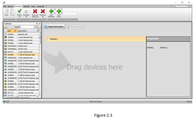
Choose “add Building”. Then will consist of building 1. Choose the 670801 7 full ip internal unit and add this option into the apartment 1. Again, choose the DE16511KAR and add into the Building 1. You can increase the apartment option until the number of apartments you want to create.
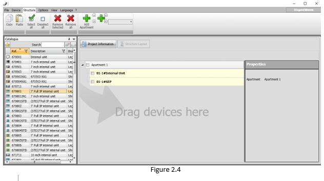
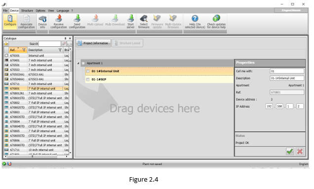
- You can see Properties options when you will choose Internal unit under the Building 1 tab
(Figure 2.4 )
IP Address: Touch panel Ip address
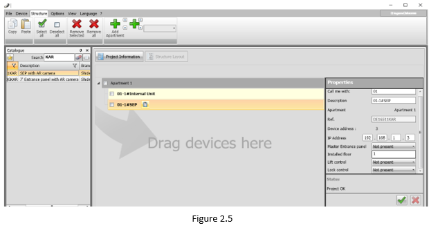
- You can see Properties options when you will choose #SEP unit under the Aparment 1 tab(Figure 2.5 )
Ip Address Intercom IP address
Chooose this icon ![]() which next to #SEP under the Building tab (Figure 2.6 )
which next to #SEP under the Building tab (Figure 2.6 )
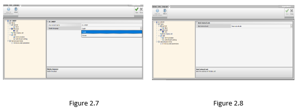
Then choose language. (Figure 2.7 )
Choose this icon ![]() which next to”internal unit list” under the Bind Intrenal unit.
which next to”internal unit list” under the Bind Intrenal unit.
(Figure 2.8 )
Check the list.
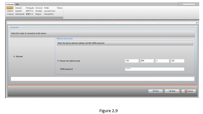
After completed the steps,Choose the 01-1 # SEP (Figure2.4) Then click The send configuration. (Figure 2.9) Write your IP address to Manual net-address input on the next page.Click the next button for İnstalling to device.
3. BTICINO INTERCOM SETTINGS FOR REZIDENCE
You must use the FULLIPSuite programs for configuration BTICINO Intercom. (Figure 3.1)
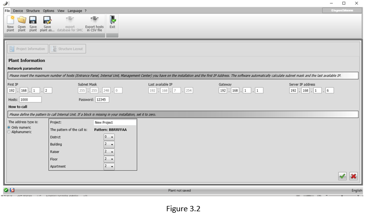
- Firstly,Run the program (Figure 3.2)
First IP= First IP for intercom to be programmed
Gateway=Gateway
District= 0 ,Bulding= 0 ,Reiser= 0, Floor= 0, Apartment= 2 then click the accept
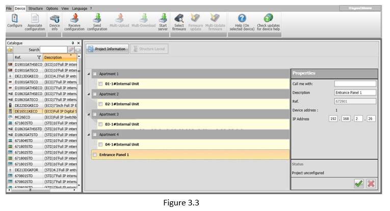
- Choose “add Apartment”. Then will consist of apartment 1. Choose the 670801 7 full ip internal unit and add this option into the apartment 1. Again, choose the 672901 and add into the Aparment 1. Choose the Appartment section for all the apartments you want create. (Figure 3.3)
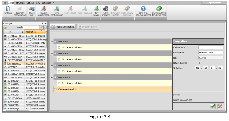
- Choose the internal unit section then Properties will open under the Apartment 1 tab.
(Figure 3.4)
IP Address: Touch panel IP address for calling with 01 via intercom.
- You can augment Apartment’s count.
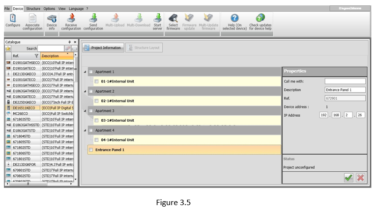
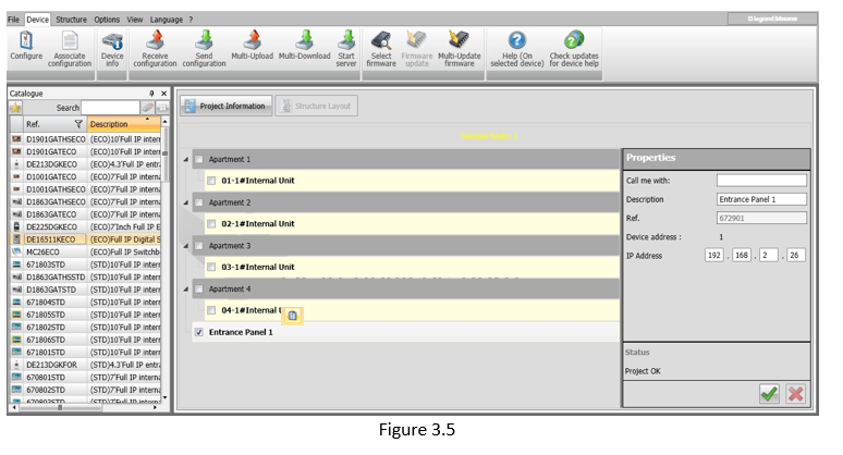
- Choose Entrance Panel section then You will see Properties Tab (Figure 3.5)
Ip Address: Intercom IP address
- Choose Entrance Panel 1 tab then Properties section will open on the right side of the windows. (Figure 3.5) Ip Address: Intercom IP address
Choose the icon which next to Enterance Panels tab (Figure 3.5)
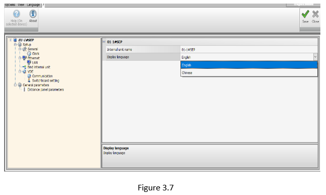
Choose the Language (Figure 3.7 )
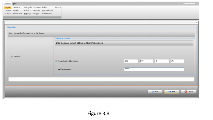
Choose Enterance Panel sectiın after completed the steps. (Figure 3.5) .Click to Send Configuration.Write IP address to Manual net-address input then click to next for install to device (Figure 3.8)

