HOW TO CREATING INTEGRATION BETWEEN INSPINIA AND AKUVOX
1.INSIPINIA TOUCH PANEL SETTINGS
- Operation voltage (24VDC)
- Communication with ethernet connection
- You need to make sure that your PC and your intercom is connected to the same network as INSPINIA .After the Inspina Touch panel is opened, 8080 is added to the end of the product IP address(Default IP =192.168.2.100) to access the product Web interface via the web browser.(Figure 1.1)
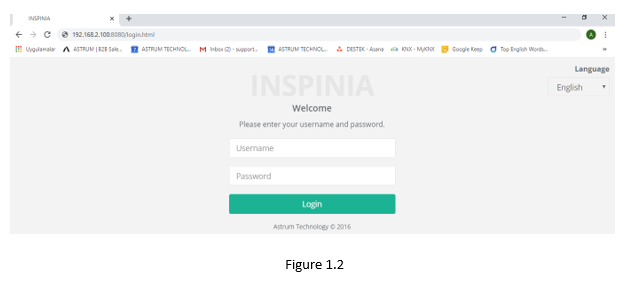
- You can access the user interface as shown in the below picture.
User interface (Figure 1.2) Username = admin / Pasword= admin (New version’s password: 4W3FVG)
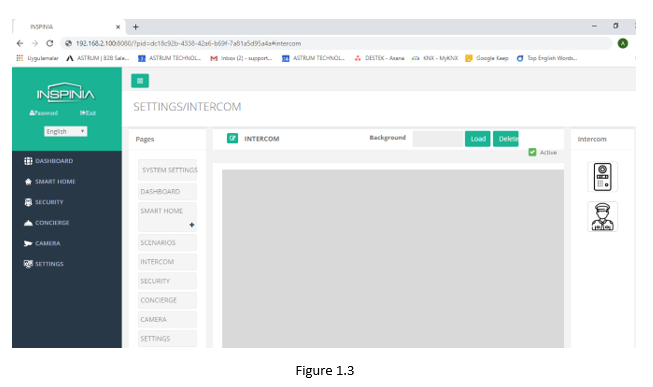
- Click the intercom tab in the settings section for configuration.(Figure 1.3)
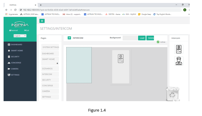
- Drag and Drop the image on the right. (Figure 1.4)
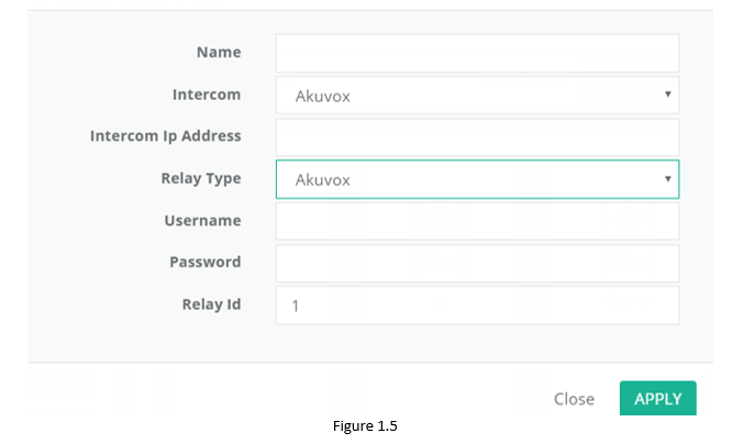
- You can make settings after double click the image (Figure 1.5)
- Name = Text the Device’s name (A Block )
- Intercom = Choose the Intercom type (Akuvox)
- Intercom Ip Address = Text the Intercom Ip Address (Akuvox)
- Relay type = = Choose the Relay Type
a) GPİO = Touch panel output control
Output = Choose the Relay output which you want to control with
b) BUS = Relay control with Bus Line
Bus Address= Ip address of the relay module
c) Ip module =Control with smart Ip relay
Ip Address= Ip address of the smart relay
d) AKUVOX= Control of the Internal relay in Akuvox
Username = Text a name which you prefer
Password= Text a password which you prefer
2.AKUVOX INTERCOM SETTINGS
- You can go to web interface of the Akuvox by write the ip addres into web browser. (Figure 2.1)
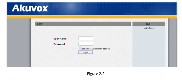
- Web Interface (Figure 2.2) Username = admin Pasword= admin
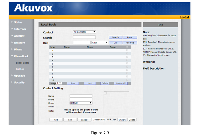
- Click to phone book/local book for make connection between Akvox and Inspinia (Figure 2.3)
Contact Setting
Name = Write a name ( 2.apartment)
Phone = Touch panel IP
Grup= Write a group name (A.block)
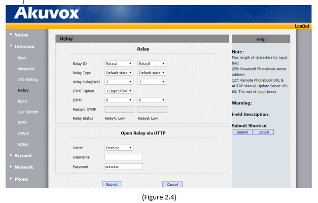
- For relay control, Open Relay via HTTP into the Intercom-Relay section(Figure 2.4)
- Switch =Switch position is Enabled
- UserName = Name of the Touch panels internal relay (Figure 1.5)
- Password = Password of the Touch panels internal relay (Figure 1.5)


